The Multilayer switches can act as IP gateway for connected hosts by providing gateway addresses at VLAN SVIs and Layer 3 physical interfaces. These switches can also participate in routing protocols ad a traditional routers does. Multi Layer switch will offer a means of preventing one switch (gateway) failure from isolating an entire VLAN. The following protocols are providing router redundancies in such ways.
- HSRP (Hot Standby Routing Protocols) is a Cisco Proprietary
- VRRP (Virtual Router Redundancy Protocol) is an IEEE standard.
- GLBP (Gateway Load balance Routing Protocol)
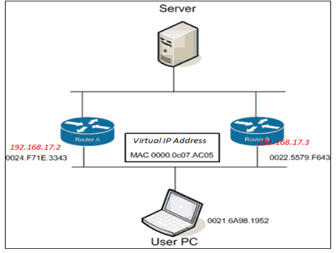
The Concept behind the HSRP, VRRP and GLBP is to establish a virtual router (its own IP Address) as the default router for the host on a LAN. The virtual router also gets a own MAC address. One or more routers then pool as the standby group for this virtual router. One of the pools is active at anytime, here actually forwarding packets sent to the virtual router MAC address if that active router disappears. Another router in the pool takes over the responsibility. The advantage is the host computer doesn’t know that different routers are involved. It just sends packets to the virtual router. Obviously the actual router forwarded those packets, and ARP will works to get the MAC address associated with the virtual routers IP address. So this is save all the ARP traffic that comes with proxy ARP, and also accommodate host implementations that ignore ARP table changes, a problem with moving a MAC address from one IP address to another(One real router’s address to another’s).

HSRP/VRRP interface configuration
Switch-A
| HSRP | VRRP |
| #Internet Ethernet 0 | #Internet Ethernet 0 |
| #Ip address 192.168.17.2 255.255.255.0 | #Ip address 192.168.17.2 255.255.255.0 |
| #standby 2 ip 192.168.17.1 255.255.255.0 | #vrrp 2 ip 192.168.17.1 255.255.255.0 |
On the second router attached to the Ethernet LAN
Switch -B
| #Internet Ethernet 0 | #Internet Ethernet 0 |
| #Ip address 192.168.17.2 255.255.255.0 | #Ip address 192.168.17.2 255.255.255.0 |
| #standby 2 ip 192.168.17.1 255.255.255.0 | #vrrp 2 ip 192.168.17.1 255.255.255.0 |
On both routers interfaces in the same subnet with common stand by group of 2 on that link. So both routers are responsibly for acting together as the virtual router 192.168.17.1.Host are configured with a static default gateway, IP address that of the virtual router 192.168.17.1.
The HSRP can be used on LAN interfaces: Ethernet, Fast Ethernet, Token ring and FDDI. On some router model and interfaces you can use multiple HSRP groups (Multiple Spanning Tree Environment).So that might be to create two virtual routers. The groups spanning two actual routers, point half of the LAN host at one virtual router and half of at the other virtual routers. When use different priorities so one actual router is active as the first virtual router and other as the second virtual router. This is load balances and if either router dies, the other one take over the responsibility for it.
The routers from Cisco 1000, 2500, 3000 and 4000 model routers with Lance Ethernet chips can only support one HSRP group per Ethernet interface and Assume this is primary limitation of the devices. There is a limitation of at most 3 standby groups (virtual routers) per Token Ring interface.
- HSRP using the mechanism UDP multicasts (224.0.0.18) periodically sends group HELLO messages (every 3 sec) to let their peers know they are still alive.
- VRRP introduced in Cisco IOS Software release 12.0 (18)ST for router. At press time VRRP is available only for the Catalist 4500 (Cisco IOS release 12.2 (31)SG),Catalyst 6500 Supervisor 2 (12.2 (9) ZA or later.
- VRRP sends HELLO messages to IP Multicast address 224.0.0.18 every 1 sec.
Once you got this basic, other HSRP commands execute here, Sets the HELLO and HOLD timers for standby group is 2.These are the default value of 1 second between HELLO and 3 seconds before assuming a router is down.
| #standby 2 timers 1 3 | #vrrp 2 timers 1 3 |
To control which router is active, configure like
| #standby 2 priority 90 | #vrrp 2 priority 90 |
The default priority is 100, higher priority will be the Active router
To allow a router to resume being the active router group 2, add
#Standby 2 preempts -This command is not necessary for vrrp it’s enabled by default when you configure VRRP.
There is also a command that lets you track the interfaces and lower the priority if any of the interfaces is down (making router less desirable as default gateway). The default increment is 10, but you can configure other increment. Incremental other than 10 are cumulative. If several interfaces are down, the configured increments are all subtracted from the priority level of the router.
To track the interface the command will be,
| #standby 2 track Ethernet 0 25 | Vrrp 2 track ethernet0 25 |
To monitor the stand by the router,
| HSRP Router | VRRP Router |
| #show standby | #debug vrrp all |
| #debug standby | # debug vrrp state |
GLBP Configuration -The Gateway Load Balancing Protocol is a Cisco proprietary protocol designed to overcome the limitation of the existing redundant router protocols. Some of the cases are the same as with HSRP/VRR, but the terminology is different and the behavior is much more dynamic.
GLBP was introduced in Cisco IOS software 12.2(14) s for Routers. GLBP is available for the Catalyst 6500 Supervisor 2 with IOS release 12.2(14) SY4 or Later and Supervisor 720 with IOS release 12.2(17) SX4 switch platform.
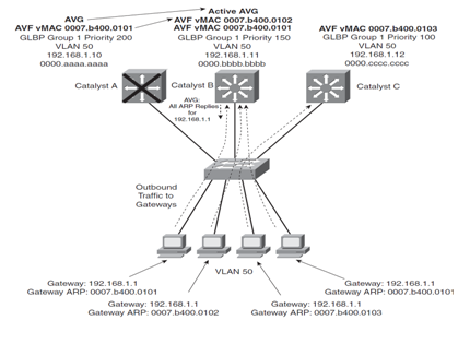
To provide a virtual router, Multiple switch (Router) are assigned ti a common GLBP group. Instead of having just one active router performing forwarding for the virtual router address, all routers in the group can participate and offer load balancing by forwarding a portion of the overall traffic. The advantage of that is, one of the clients has to be pointed toward a specific gateway address, and they can all have the same default set to the virtual IP address. The load balancing is provided completely through the use of virtual router MAC addresses in ARP replies returned to the client send an ARP reply with the virtual MAC address of a selected router in the group. The result is that all clients use the same gateway address but have different MAC addresses for it.
To configuring GLBP,
Switch-A
#Catalyst A(config) #Interface Vlan 50
#Catalyst A(config) #Ip addresses 192.168.1.10 255.255.255.
# CatalystA (config) #glbp 1 ip 192.168.1.1
#CatalystA (config) #glbp 1 priority 200
#CatalystA (config) #glbp 1 preempt
Switch-B
#Catalyst B(config) #Interface Vlan 50
#Catalyst B(config) #Ip addresses 192.168.1.11 255.255.255.0
#CatalystB(config) #glbp 1 ip 192.168.1.1
#CatalystA (config) #glbp 1 priority 150
#CatalystA (config) #glbp 1 preempt
Switch-C
#CatalystC (config) #Interface Vlan 50
#Catalyst C(config) #Ip addresses 192.168.1.12 255.255.255.0
#CatalystC(config) #glbp 1 ip 192.168.1.1
#CatalystA (config) #glbp 1 priority 100
Note: GLBP group range; 0-1023
The router priority;1-255 ( default -100)

Behind this load balancing, one router is elected the (AVG) Active Virtual Gateway .This router has the highest priority value or highest IP address in the group, if there is no highest priorities. The AVG answer all ARP request for the virtual router address. Which MAC address it returns depends on which load-balancing algorithm it is configured to use. In any case, the virtual MAC address supported by one of the router in the group is returned.AVG also assign the necessary virtual MAC addresses to each of the routers participating in the GLBP group. We can make four MAC addresses in group. Each of these routers is referred to as an Active Virtual Forwarders, Forwarding traffic received on its virtual MAC address. Other routers will be back up if one fails.
AVF (Active Virtual Forwarder); Each router participating in the GLBP group can become AVF.The virtual MAC address always have the form 0007.b4xx.xxyy number. The first 16bit denoted by xx.xx represents six zero bits followed by a 10 bit GLBP group number. The 8 bit yy is the virtual forwarders number.


